The Issue of Efficiency
A primary concern for any maglev is the efficiency of the levitating system. Unlike the German and Japanese maglevs, the Inductrack requires no power to produce its magnetic field, because it uses permanent magnets. Therefore, this particular source of inefficiency is not an issue. To levitate the train car, though, currents must be induced in the track's circuits, and electrical resistance in the circuits will dissipate some of the power, converting it to heat. This power loss, coming as it does from the motion of the train relative to the track, will result in drag forces. These drag forces are the magnetic counterpart of the frictional drag associated with wheels and bearings in a conventional train. In the Inductrack, the magnetic drag forces vary inversely with the train's velocity, becoming very low at typical maglev speeds (250 to 500 kilometers per hour). These drag forces thus behave in an opposite way to wheel-frictional drag forces or aerodynamic drag, both of which increase with rising speed.
In aircraft, a common way to gauge the performance of an airfoil is to calculate its lift-to-drag (L/D) ratio-the ratio of its lifting power to its aerodynamic drag. At typical flying speeds, the L/D ratio of the wing of a jet aircraft is about 25 to 1 and does not vary much with velocity. In the Inductrack system the corresponding ratio relates magnetic lift-the levitating force-to magnetic drag. We were able to find a formula for the Inductrack's L/D ratio by performing a detailed theoretical analysis of the system. Much help came from my coworker at the Livermore laboratory, Dmitri D. Ryutov, formerly at the Budker Institute of Nuclear Physics in Novosibirsk, Russia. Ryutov is recognized internationally for his contributions to the theory of magnetically confined plasmas for fusion, and he applied techniques from that discipline to his analysis of the Inductrack.
We found that the Inductrack's L/D ratio is directly proportional to the speed of the moving Halbach arrays. When the train is at rest, there is obviously no levitating force, and the L/D ratio is zero. But as the train begins to move, the levitating force rises quickly, reaching half its maximum value at a speed between two and five kilometers per hour. We call this the transition speed-at this velocity, the magnetic lift and drag are equal. At twice the transition speed, the levitating force reaches 80 percent of its maximum value and the L/D ratio rises to about five. Thus, we see that the Inductrack's levitation becomes effective when the train is moving very slowly. If the cars are equipped with auxiliary wheels, the train can run on rails until it reaches the transition speed, at which point it would begin levitating. Furthermore, the system's efficiency continues to improve as the train gathers speed-the L/D ratio can reach values as high as 200 to 1 at a velocity of 500 kilometers per hour. And if the drive power suddenly fails, the train cars would remain levitated while slowing down to a very low speed, at which point the cars would come to rest on their auxiliary wheels.
Another way to evaluate the efficiency of the Inductrack maglev system is to measure the power loss from magnetic drag and compare it with other power losses. With a 50,000-kilogram train car running at 500 kilometers per hour, about 300 to 600 kilowatts of power would be dissipated in the track's levitating circuits. In contrast, the aerodynamic drag on the train car at that speed would cause a power loss of nearly 10 megawatts. In other words, the power needed to keep the train car levitated is less than one tenth of that required to overcome wind resistance.
Drive Systems for the Inductrack
Thus far I have described only one type of Inductrack circuit-namely, a row of rectangular coils. The track, however, might take many other forms, depending on the performance that is desired. For example, the track could consist of stacks of thin sheets of aluminum, with insulating films placed between the layers. When the Halbach arrays move above these stacks, the magnetic fields would induce electric currents in the aluminum sheets. A series of parallel slots would be etched into each sheet to create the optimal path for the electrons, minimizing eddy currents that would increase power losses. Such a track would exert a greater levitating force than a row of rectangular coils would, and it might also be cheaper to manufacture.
Another alternative is to increase the track's efficiency through a method called inductive loading. It can be applied to the rectangular circuits by placing tiles of ferrite-a magnetic ceramic containing iron oxide-around the bottom section of each coil. This change would decrease the current induced in the coils by the Halbach arrays and hence cut the power loss caused by electrical resistance. Because the magnetic drag would be lower, the magnetic lift would overcome it more easily, and the train would begin levitating at a lower transition speed. Inductive loading involves a trade-off, though: it would reduce the system's maximum levitating force below the 40 metric tons per square meter that is possible with the simpler track construction.
One of the virtues of the Inductrack is that it could accommodate a wide variety of drive systems for the trains. If the track can be hooked up to a power grid, the train cars could be propelled by "drive coils" interspersed among the track's levitating circuits. Supplied with current from the grid, the drive coils would generate electromagnetic fields that would interact with the fields from the Halbach arrays. Pulsing the drive coils in synchronization with the train's motion will result in accelerating or decelerating forces on the train cars. In situations where electrification of the rail line could be too expensive-for example, in rural areas between distant cities the maglev train could be equipped with a shrouded propeller driven by a gas turbine. Because wind resistance would be the only significant drag force on the train, a single propeller would be sufficient to accelerate the maglev to high speeds.
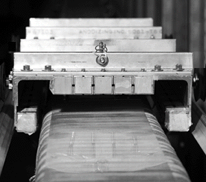
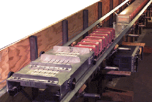
| WORKING MODEL of the Inductrack constructed at Lawrence Livermore National Laboratory to test the system's performance. The first section of the 20-meter-long track contained electrically powered drive circuits to accelerate a 22-kilogram cart (below). Once set in motion, the Halbach arrays on the underside of the cart allowed it to coast over the 1,000 levitating coils in the second section of the track (inset). |  |
After we completed our theoretical analysis of the Inductrack, our team proceeded to the next logical step: building a small working model of the system. Its purposes were to check the theory's predictions and to demonstrate stable levitation. The 20-meter-long test track was designed to levitate a 22-kilogram cart equipped with Halbach arrays on its underside. The first section of the track contained electrically powered drive circuits; the second section consisted of 1,000 thin, rectangular levitating coils, each about 15 centimeters wide.
At the start of each test run, the cart rolled on its auxiliary wheels over the drive circuits, which accelerated the vehicle to a speed of 12 meters per second. This was sufficient to allow the cart to levitate above the rectangular coils (the track's transition speed was only four meters per second). The cart coasted over nearly the whole length of the track before settling on its wheels at the far end. We measured the cart's velocity and oscillations using two pointer-type lasers that were mounted on the cart at a slight angle to each other, like a pair of crossed eyes. The lasers illuminated spots on a white screen at the end of the track; analysis of a video-camera record of the spot separations and locations yielded plots of the cart's position and its pitch-and-yaw motions.
The tests verified our predictions of the Inductrack's performance and proved that the concept is workable. What is more, a preliminary feasibility study conducted in 1997 by the consulting company of Booz-Allen & Hamilton concluded that a full-scale Inductrack system would be less expensive to build and operate than the German maglev. For example, the study estimated that a train car equipped with Halbach arrays would cost between $3.2 million and $4.2 million, whereas a car in the German maglev would cost more than $6 million. (The estimated cost of a Japanese maglev car has not been made available.) The Inductrack vehicle would be more expensive than a conventional railcar, which costs between $2 million and $3 million, and building the system's track could cost as much as 80 percent more than constructing an ordinary track. The study noted, however, that the Inductrack's energy usage and maintenance costs would be significantly lower than those of a conventional railway.
